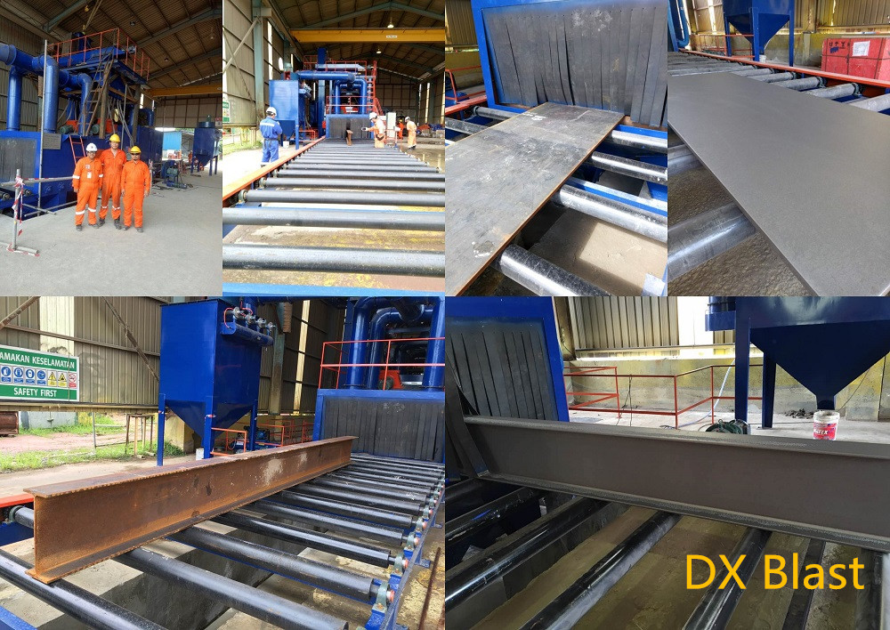
The roller conveyor shot blasting machine adds a specified number of workpieces in the finishing room. After the machine is started, the workpieces are driven by the drum and start to turn over. The bullet beam formed by the high-speed projectile thrown by the blasting machine uniformly impacts the surface of the workpiece to achieve the purpose of finishing. The thrown bullets and sand particles flow into the steel mesh at the bottom through the small holes on the rubber track, and are sent to the elevator through the screw conveyor, and the elevator is lifted into the separator for separation.
The dust is sucked by the fan and sent to the dust collector to be filtered. The clean air is discharged into the atmosphere. The dust on the cloth bag is mechanically shaken and falls into the dust box at the bottom of the dust collector. The user can remove it regularly. The waste sand flows out from the waste pipe. Users can recycle. The shot-sand mixture is recycled into the chamber through the recycling pipe, and clean shots will enter the shot blasting device through the shot supply gate to hit the workpiece after the separator is separated.
This machine is in the shape of no ground pit, and the installation can be carried out after checking the horizontal, vertical and horizontal plane with a level before installation. The finishing room, shot blasting device and other parts have been assembled into one body before the machine leaves the factory. When the whole machine is installed, follow Figure 1 to fasten the lifting machine and the lifting machine on the finishing room with bolts. When using bucket hoisting equipment, attention should be paid to adjusting the bearing seat of the upper driving pulley to keep it level to avoid belt deviation. Then fasten the serial number 1 separator and the upper part of the elevator with bolts.
Place the pellet supply device on the separator, insert the pellet recycling pipe into the steel pipe behind the sorting room, and connect all the pipes according to the dust removal system diagram. After separation, users can bring their own waste bucket for disposal. The device diagram of the separator. When the separator is in normal operation, there should be no gaps in the projectile flow curtain. If it cannot form a full curtain, the serial number should be adjusted until the full curtain is formed to obtain an outstanding separation effect. The bulk material behind the projectile sieve should be removed regularly.
Post time: Jan-11-2021
